2h LED hack
Recently, I got myself a little “WS2812 LED Pixel Controller” from AliExpress. The Controller is called “SP501E”, did cost around €8 and is supposed to be a “smart Wi-Fi device”. Therefore, I suspected an ESP8266 controller inside it, and I may be able to use my own firmware with it. I was right, and so the SP501E is now part of my Home Assistant without any cloud.
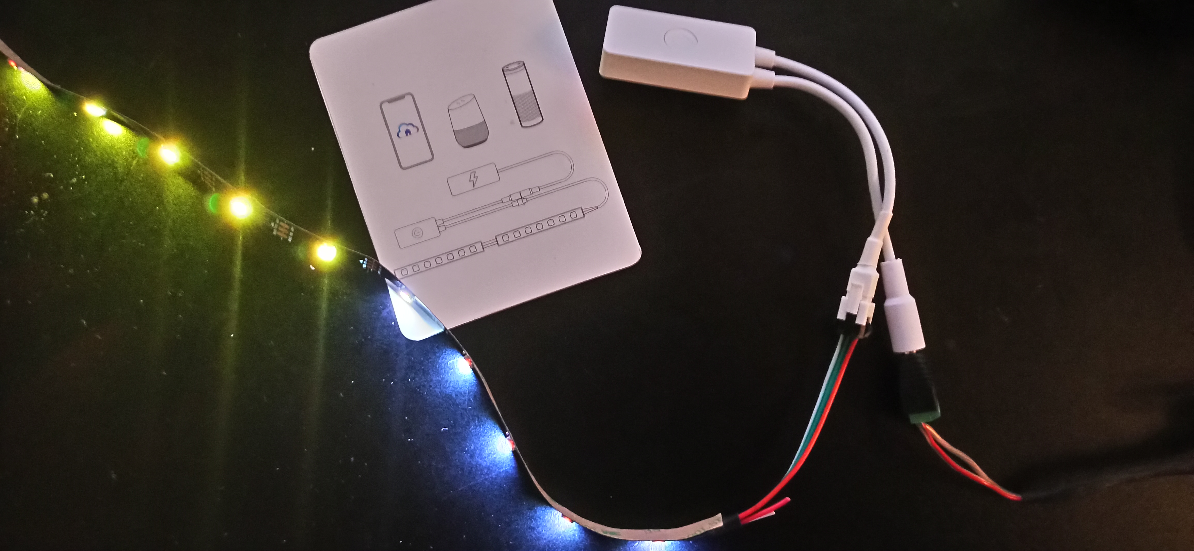
Unboxing and the original app
The controller arrived, and at first, I tried to use it with the App provided. You need an app, register within the app, and it seems that the controller needs internet access. The available effects are pretty basic, external control seems impossible. In short: Not really usable for me.
The Module itself comes with a power button, an 3-pin JST Plug as they are used by default on WS2812-stripes, and a standard DC Jack. The enclosure feels okay for the price tag.

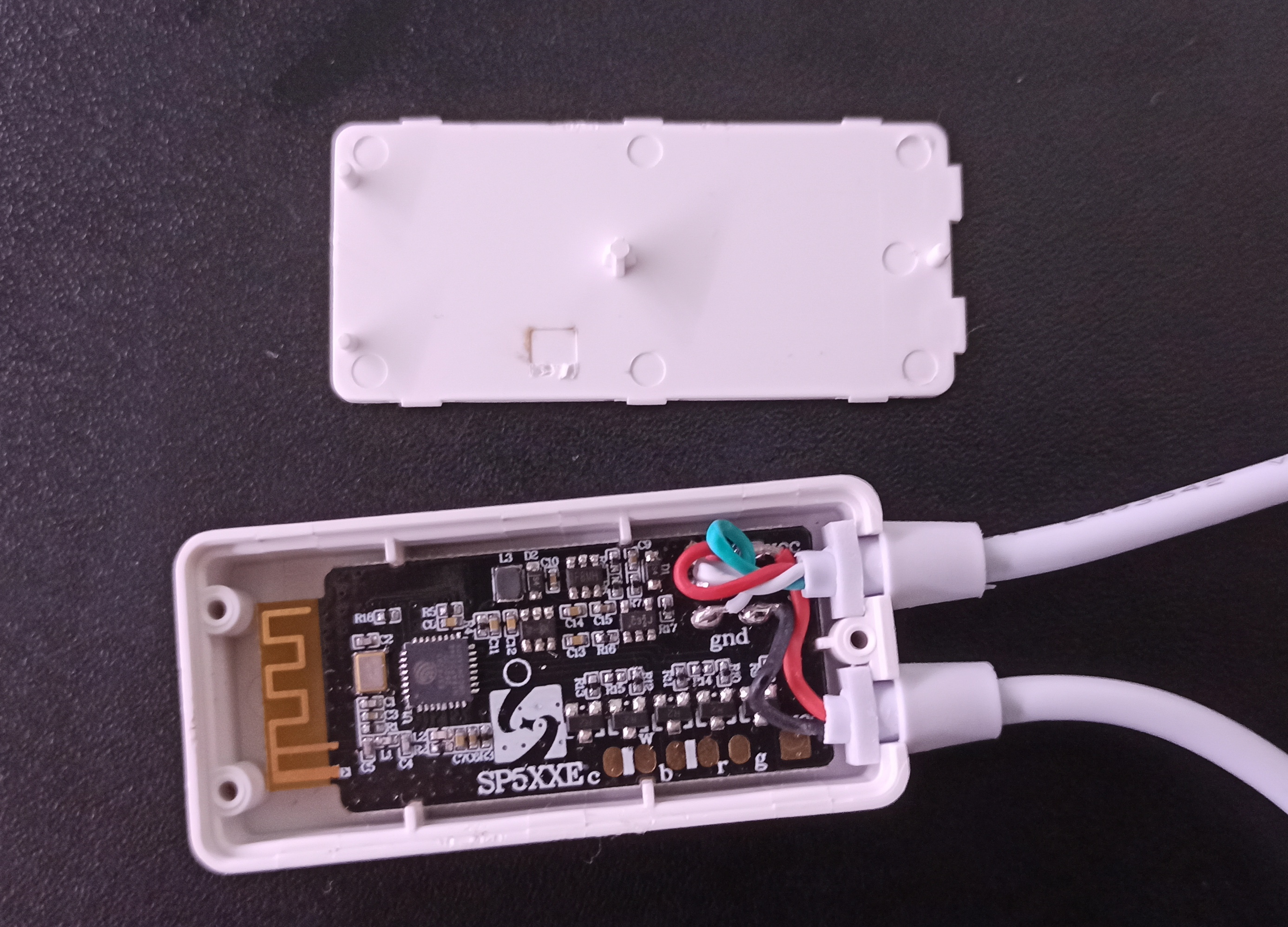
Looking inside
As stated before, I suspected an ESP8266 inside. The enclosure is pretty easy to open up with a screwdriver. Inside, there is in fact an ESP8266. You also notice a bunch of solder pads. It seems that the same PCB may be used for analog RGBW LED Stripes as well.
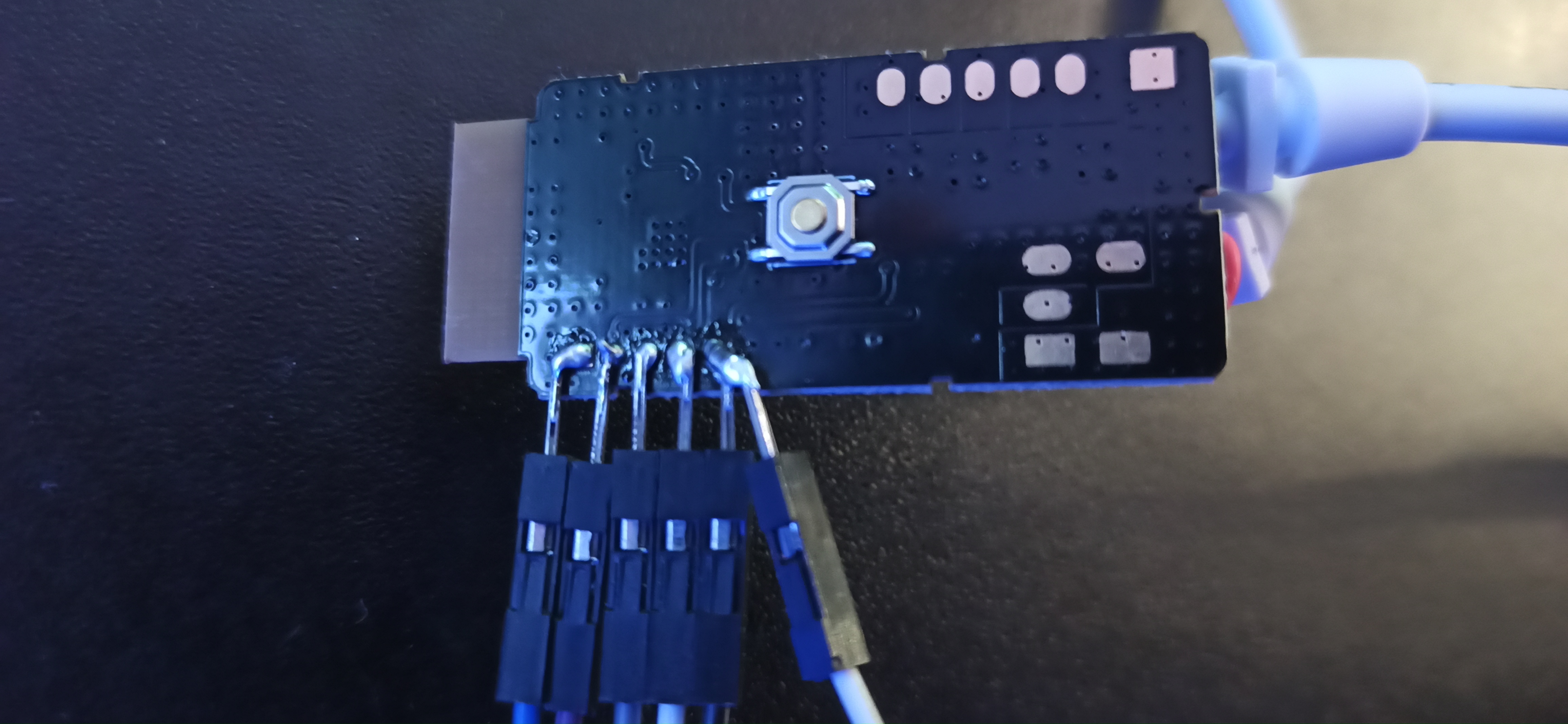
On the back side, the programming pins are exposed on some solder pads. They are not labeled, but thankfully, Operation760 reversed engineered them on GitHub
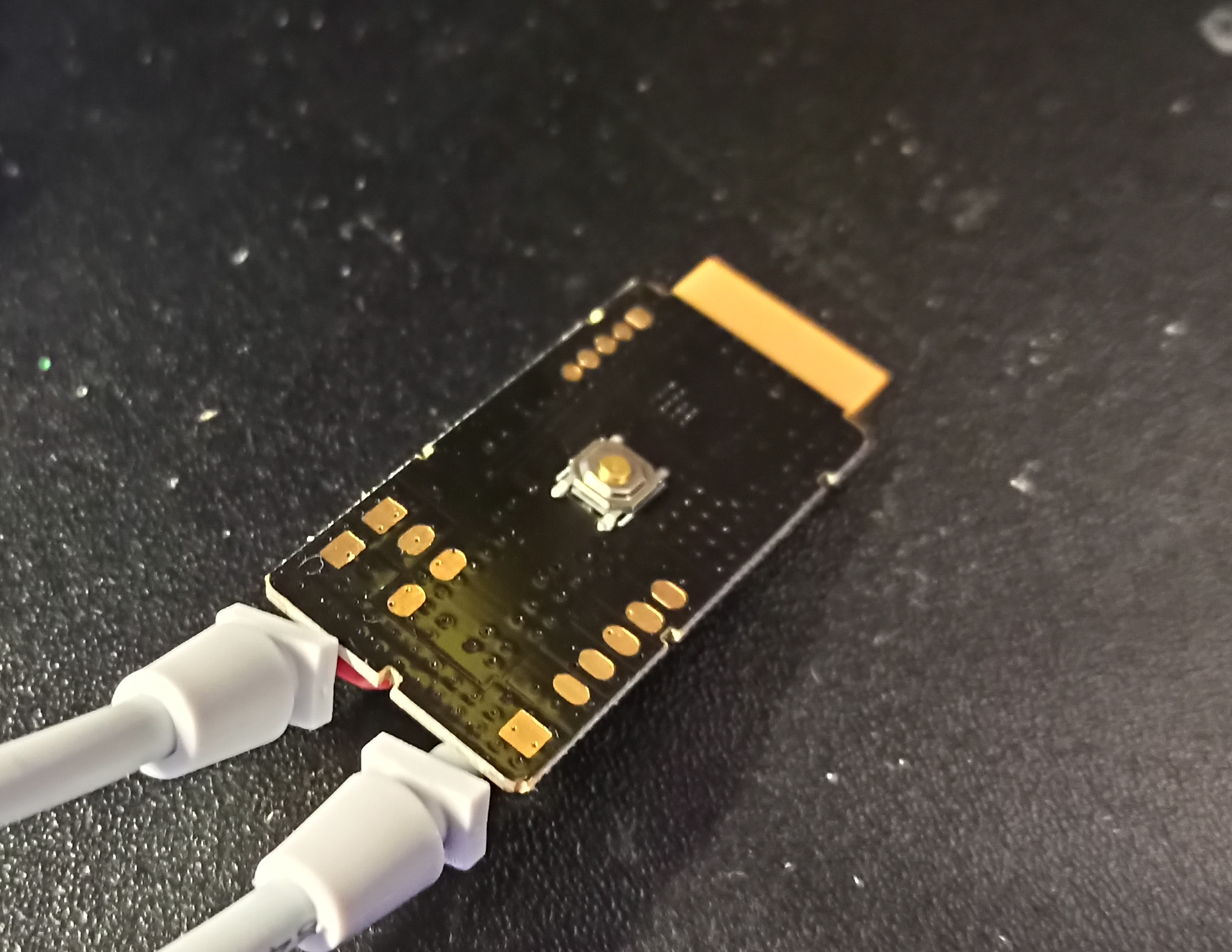
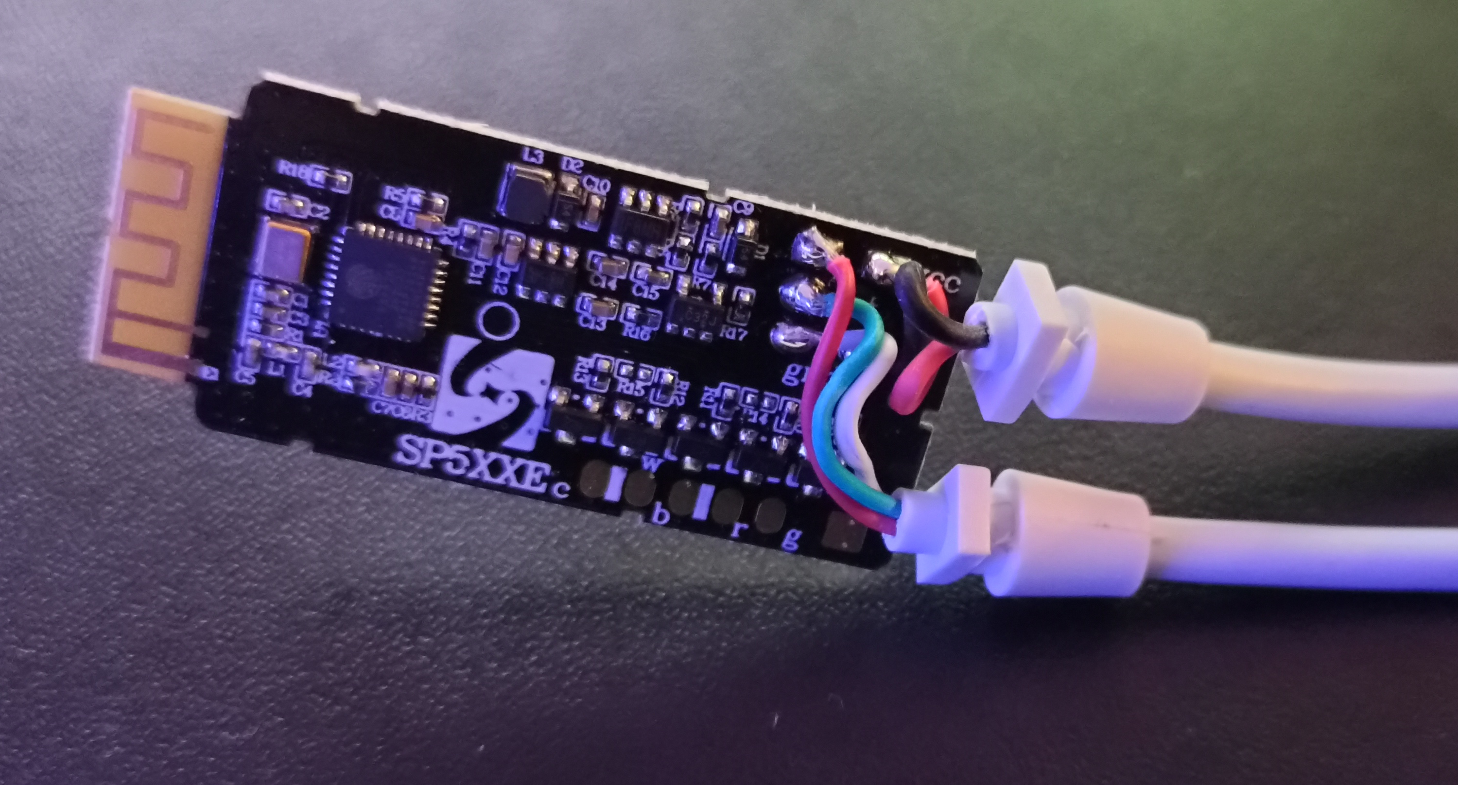
Unfortunately, the PCB won’t fit into the enclosure with cables or headers attached. That means, you have to attach/remove the cables each time you have to flash firmware via non-OTA.
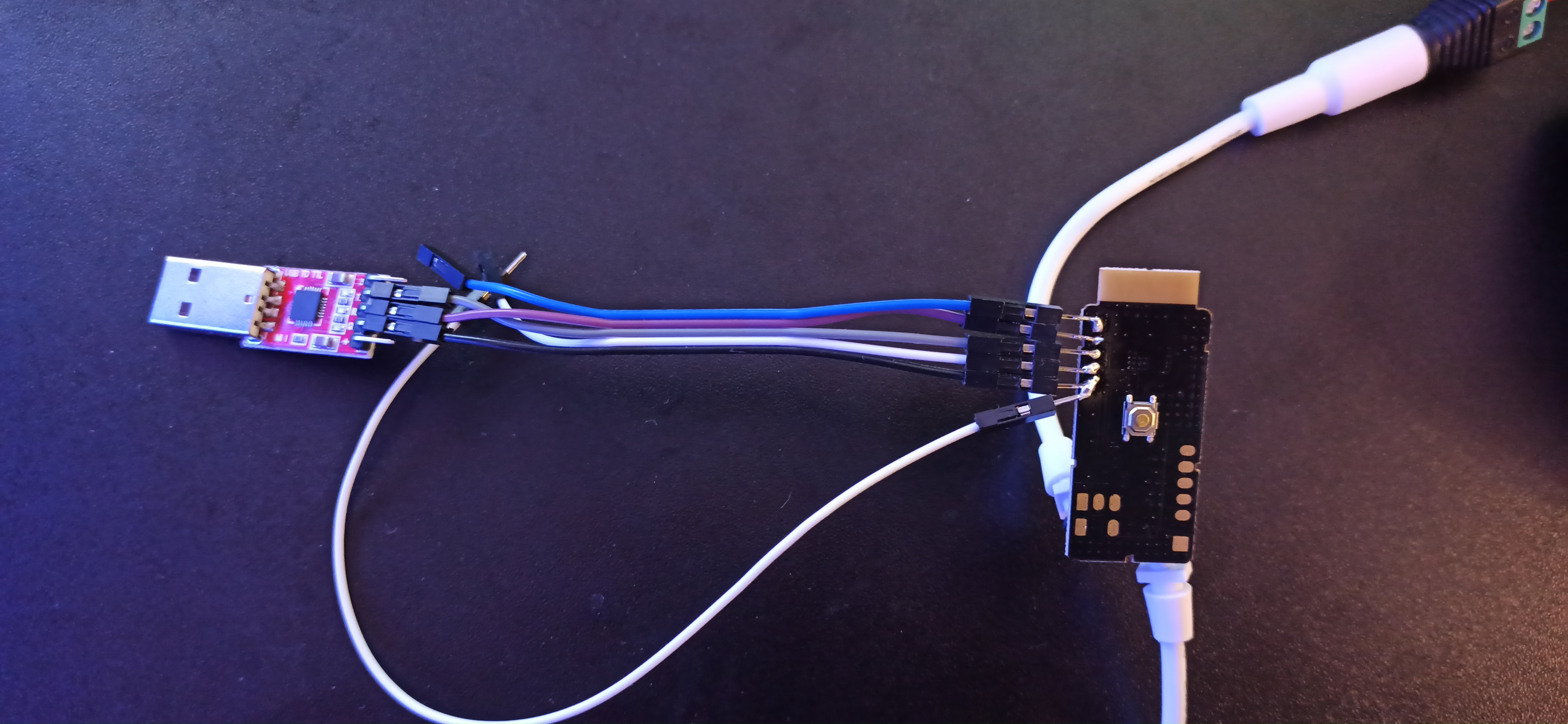
I connected jumper wires as shown in the image. I got stable results when using power not via the jumper, but via the DC Jack. That means you’ll have to connect GND, RX and TX to a USB-UART Adapter. As the ESP8266 runs on 3.3V, take care that the output of the UART Adapter is 3.3V, not 5V. I also connected a Jumper to IO0, with the other part connected to GND, as you need manually connect/disconnect IO0 and GND (white jumper wires in the picture).
The Firmware
As firmware, I currently use ESPHome for my DIY-SmartHome-Devices. ESPHome features a native integration into HomeAssistant, and has a very modular high-level configuration that allows you to generate firmware for your custom device without coding.
Of course, you may use any other firmware, or building your own using Arduino or PlatformIO. I strongly recommend using a working OTA (Over-the-Air)-Upgrade mechanism to allow for firmware upgrades without soldering. As the SP501E has only 1M Flash, you’ll probably need to select a board called esp01_1m in PlatformIO. For OTA to work, the firmware size must not exceed half of the flash size.
I used the following ESPHome-Configuration:
esphome:
  name: rgb_test
  platform: ESP8266
  board: esp01_1m

wifi:
  ssid: "iot.margau.net"
  password: "no-i-will-not-tell-you"

# HASS API
api:

# Allow API
ota:

# Print Updates
logger:

# up to 150 lights on GPIO3 with some effects
light:
  - platform: neopixelbus
    type: GRB
    pin: GPIO3
    num_leds: 150
    name: "RGB Test"
    effects:
      - addressable_scan:
      - addressable_color_wipe:
      - addressable_rainbow:
      - addressable_fireworks:
          name: Fireworks Effect With Custom Values
          update_interval: 32ms
          spark_probability: 10%
          use_random_color: false
          fade_out_rate: 120

# WebServer component, displays some information
web_server:
    port: 80

# enclosure button, no action implemented here, may be used for HASS automation
binary_sensor:
  - platform: gpio
    pin:
      number: 1
      inverted: True
    name: "RGB Power Switch"
Of course, you may expand the functionality, e.g. react to a button press directly on the board.
Put this into a yaml-File (e.g. rgb_test.yaml), and use the usual ESPHome Magic on your command line:
esphome rgb_test.yaml compile
Then, you’ll need to program the SP501E. That will happen, as usual with the ESP8266, in the following way:
- Power Off (unplug DC Jack)
- Connect GPIO0 with GND Jumper
- Plug USB-to-UART into your computer, make sure you know which UART to be used (e.g.
/dev/ttyUSB0) - Power on SP501E
- Program the Chip:
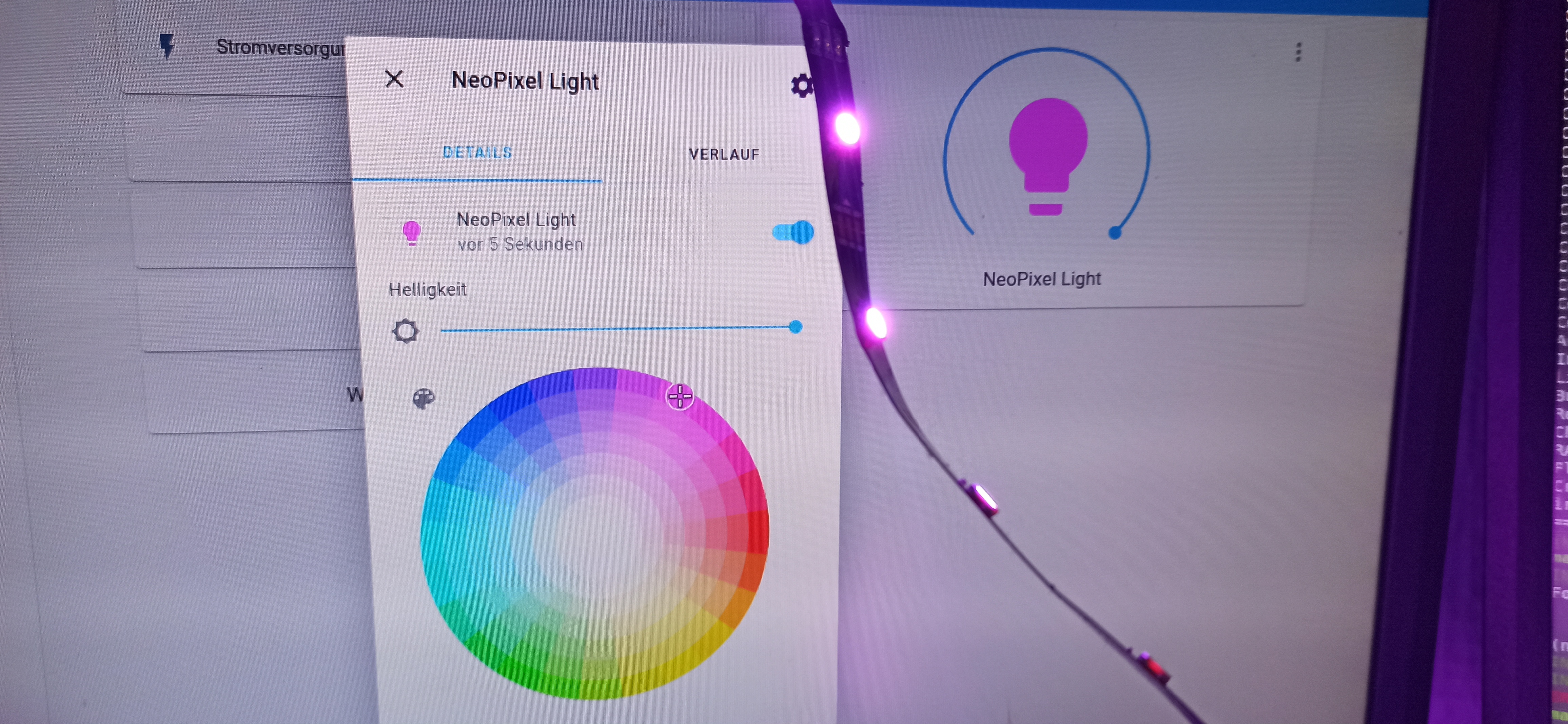
esphome rgb_test.yaml upload. If asked for an interface, select the Serial interface from 3 - After successful flashing, remove GPIO0-to-GND connection, and power cycle the board. It should now connect to your Wi-Fi specified in the config. You may watch the serial output with a serial monitor of your choice (Interface from 3 again). I usually use GtkTerm under Linux. You may connect some LEDs, connect to the device IP in browser and test them out.
It’s also useful to test out an OTA-Update before removing the Programming wires.
If everything works, you’re ready: Remove the Jumpers, put the PCB into the enclosure again, and have fun with your lights!
Conclusion and Outlook
In my opinion, the SP501E with custom firmware is a nice tool for home automation and similar use cases. The Flash is a bit low, and for this price you should not expect wonders. Especially the flash is not really sustainable. The flashing process is straightforward, although you’ll need some soldering. I ordered a few more of these, and calculate with 15-30 minutes for one board when doing in bulk. The result is definitively way more elegant solution than working with development boards, and the enclosure is suitable for a home environment.
I’ll probably use them for some “secondary”, more static lightning solutions. For primary WS2812 use-cases (e.g. stage with around 25fps animations), I’d avoid using Wi-Fi and the ESP8266, although I did this before. When additional boards will arrive, I’ll also try out the WLED-Firmware, which looks interesting for ArtNet-Support etc.